UML: Use Case Diagram
UML: Use Case Diagram
Introduction
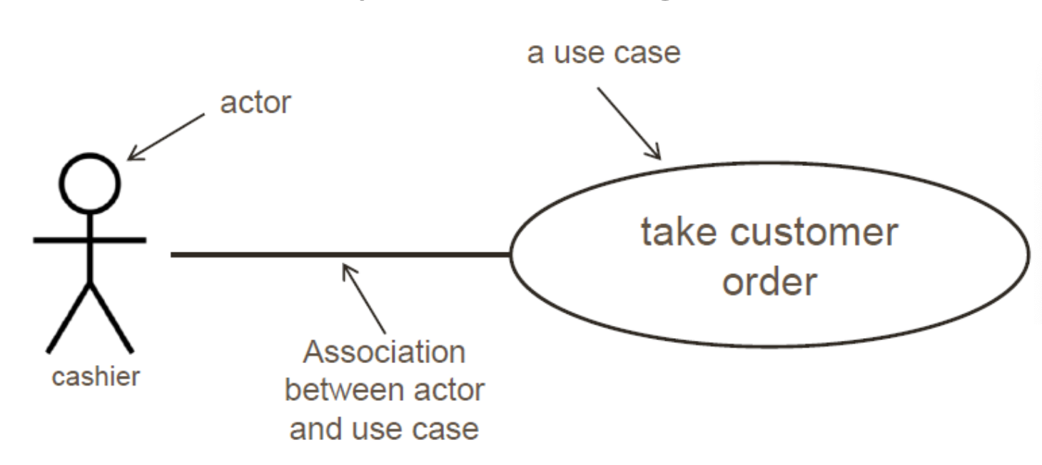
A use case contains 2 elements:
- Actor: The actor is outside the
system boundary. - Use case: A use case shows what a system does(what the actor can do with the system), not how it does it.
These 2 elements interact with each other using relations. For example:

Relation
1. Generalization
Both actor and use case can be generalized. For example:

To validate client, we can use three differet ways(Validate Client is like an interface in Java, which has three implementations):
- Check Password
- Check Thumbprint
- Verify Retinal Scan
2. <<extend>>
<<extend>> can only be used for use cases(actors cannot use this relation). And it indicates an optional relationship between two use cases:

The extending use case extends the behavoir of the base use case. In the above picture, Pay For Food is the base case, and Print Receipt is the extending case. In the case of paying for food, we can have an option to print the receipt(We can also choose not to print the receipt).
3. <<include>>
<<include>> can only be used for use cases(actors cannot use this relation):

In the case of deleting book, the administrator firstly need to search book. In order to be complete, the case Delete Book should include the case Search Book.
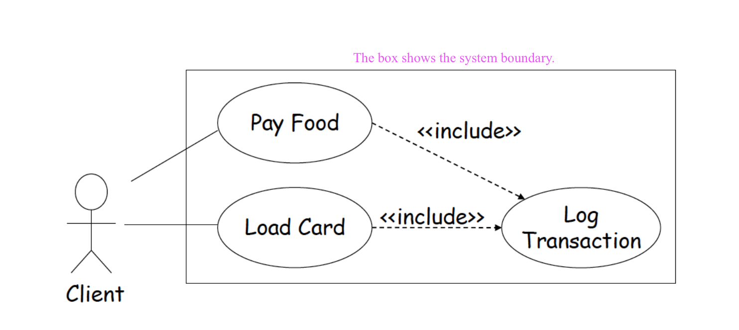
System Boundary
Note that when drawing the use case diagram, it is recommended to add the system boundary:
